
Painting a polycarbonate body shell
Introduction
This guide will give beginners and experienced modelers an aid to help to apply a smart and durable design to a
precious body shell. It aims to help avoiding mistakes, so that the joy of the self-made design will last as long as
possible.
Basics
There are two different methods to paint a polycarbonate body shell, either with spray cans or with an airbrush. The
priority here should be addressed to working with spray cans, because approximately over 90% of all car bodies are
painted with spray cans!
Spray cans
Quick and easy painting is the biggest advantage of the spray can. With spray cans large areas are done quickly, you
don‘t have to clean up any paint guns. Sometimes the can ridiculed as a beginner‘s tool.
However, when painting with a can is properly mastered, really amazing results can be achieved.
RC-Paint Spray Gun
Convert your spray can into a spray gun. The long-lever system of this handle makes using a spray can much more convenient and provides better flow rate control as well.A few words about health ...
Even though it is common sense we‘ll address it here briefly again. Use respirators when painting,
no matter what kind of paint you use. There‘s no need for a professional mask with removable filters. A mask that
covers nose and mouth ranges will do. The suspended particles will be effectively retained.
In this context, our product is recommended for Lexan RC Paint color. This is in contrast to many other populated special Lexan lockups, environmental and Physiologically acceptable propellant.
Two rules:
- Wear a respiratory mask for every paint job, even small ones.
- 2. Paint in a well ventilated area, or better yet outdoors.
Preparation of the workplace
Since you certainly want to achieve a proper result the paint booth should be as clean and dust free as possible.
Otherwise, fine dust particles will settle on the body shell and affect the outcome.
Of course spray mist removal by suction would be best, but who has that kind of equipment available!? Compressed air
spray
cans work fine for dust removal as well.
You should also have available:
- Kitchen roll or a lint-free cloth
- Isopropyl or cleaner‘s naphtha. Do not use spiritus under any circumstances, because this removes the plasticizers from the body shell!
- The previous day‘s newspaper. You may still want to read today‘s issue...
- y0544 Abrasive fleece Microfine Gold Pads
- Schneider Permanent marker
- Compressed air spray
- Scissors for polycarbonate, curved or straight
- A cutter knife or a pointed scalpel with a new sharp blade.
- A step drill or a conical reamer
- Use only high quality masking and edge tape
- The selected color RC 1005 to RC 1014 (RC-Paint polycarbonate paint is known to be very economical! A 150 ml can lasts - depending on the intensity of the paint application - for one 1/8 scale body shell or about two in 1/10 scale. Usually two to three cans will do for a 1/6 or 1/5 body shell)
- Respiratory
- y1481 RC-Paint Spray Gun
Preparation of the body shell
Before starting the actual painting some preparations are necessary to prevent bad surprises. Body shells are often
sold with a protective sheet. Remove this sheet and lay it gently spread with the sticky side up in an adjoining
room to prevent contamination.
We‘ll need it later. Recently, the body shells come with a semi-transparent protective film on the outside. This
film does not need be removed.
Cutting the body shell
This paragraph applies to those who want to drive their car; therefore the engine needs some air. The windows and
other required holes must be cut out! Special scissors for polycarbonate are the safest tool for this job.
Round holes
Round holes are pre-drilled to a small diameter and then expanded to the desired diameter with a reamer or a step
drill by hand. This has the advantage that has larger holes will be actually round instead of triangular.
Bild 1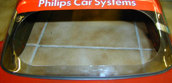 |
Bild 2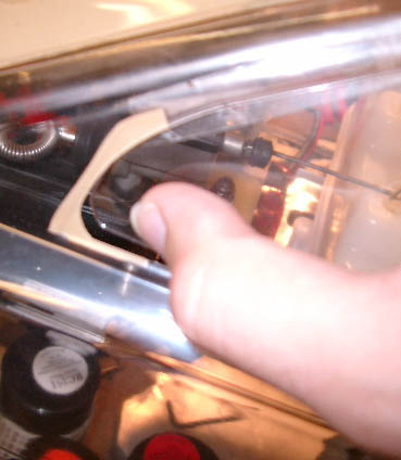 |
The windows ...
Here's how it‘s done quickest and smoothest: Take the scalpel and carve with reasonable pressure (not just scratching!)
carefully along the contour where the windows are to be removed. It should be carved from the outside! This contour
can have any layout you want, for example the complete window removed, a round hole or a turned down window.
Take care that you create smooth rounded layouts only, no sharp corners. Sharp corners will start cracks in
case of a collision.
The same applies to the rear window.
The cut-out should be as large as possible, but go for large radii in the corners. Helpful for the large opening is
a circle with metal tip or a circle cutter. This helps for marking perfect large radii. (Picture 1)
After the contours are carved bend the plastic along those lines. After a few attempts the material will break along
the line. Starting from this point the windowpane can be squeezed out towards the inside. (Picture 2)
If, however, the carving wasn‘t deep enough, or one has slipped with the knife, it can happen that the material
tears uncontrollably. So, even if it sounds nice and easy, you should work very carefully.
Now, if all panes have been removed as required, the sharp edges of the cuts should be deburred with abrasive fleece
to prevent injuries in the future!
Bild 3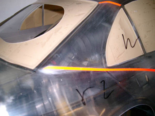 |
Sanding the body shell
Next the body shell should be roughened slightly on the inside! Clear body shells are always painted from the
inside.
Buff the inside of the body shell using abrasive fleece. Take care to stay away from the windows, unless you want to
paint them as well (looks odd!).
The abrasive fleece will leave superfine scratches, but since the paint will be applied from the inside, these are
later completely invisible. Some people use sandpaper for roughing. However,
this is not as useful because sandpaper leaves much deeper traces. If you want sharp color edges make sure that you
have no deep scratches. Otherwise it may happen that the paint creeps under the masking tape into the scratches and
the lines are ruined.
This is usually no problem with abrasive fleece, but better be safe than sorry. (Picture 3)
Once the body shell is completely prepared, the remaining of the abrasive fleece must be removed. This is best done
with a compressor or acompressed air spray can.
Cleaning the body shell
The moulds used in the manufacturing process of the body shells are usually treated with silicone release agent for
better removal of the finished shape. This causes a thin film on the surface of the shell, which badly affects the
adhesion of the paint.
You need:
- Mild detergent
- paper towel or lint-free cloth
Bild 4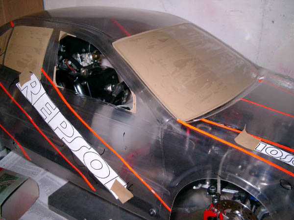 |
Masking the windows
Now it‘s time for the windows. They are supposed to remain transparent.
This time we will need:
- masking tape
- Sharp cutter knife or a scalpe
The windowpanes, where they are not already cut out, must be completely covered with masking tape. And this should be done as clean as possible, without wrinkles etc.
In the inner section of the masked area wrinkles are OK, just at the edge regions, respectively, the cut edges of the windowpanes must be smooth, because these are the sections where the paint will try to undermine the masking tape. Is everything is generously covered, cut the tape along the window frame with a knife (and only the masking tape, not the body shell) and remove the excess tape. The result should be a clean edge. (Picture 4)
For specific contours and stripes a special edge tape is recommended. Now the paths separate for monochrome and in multi-colored designs.
Bild 5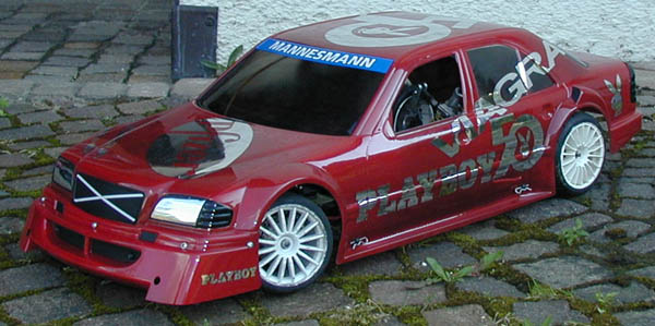 |
Monochrome designs (Picture 5)
In this variant, only the outer surface is protected from spray and then begin the painting.
Body shell preparation
Cut-out windows and mounting holes etc. are well-sealed from the outside with masking tape so that no spray will
come through. The protective sheet will no be placed on the body shell again (where applicable).
All areas not covered by the sheet are taped with masking tape, as well as the edges of the body (wheel arches,
sills, etc.). The tape should extend about 1 cm above the edge, but should not bend or adhere to the inside.
The milky transparent protective film does not need further treatment, except at points where the film is slightly
peeled off. There is also a paint-on masking sheet" available.
This is simply applied to the surface to be covered and removed after painting. But the liquid masking is not
suitable for exact dividing lines, only for large areas (e.g. windows or interiors).
After a final check of the edges of the windowpane masking, it can really start now.
Paint preparation
The paint needs preparation too.
In addition to the desired colors you should have:
- A hairdryer or a pot of heated water. Use either of them to warm the can(s) to a temperature of 40-45 ° C prior use. This is an advice for the perfectionists. Normal room temperature actually works without problems.
Applying the paint
Maintain a distance of about 30 cm between can (e.g. RC-Paint lexan paint) and body shell.
A closer distance may cause the paint to run. The first coat should only be a very light but uniform. Allow to dry
for about 5 minutes only and then apply additional light coats in a cross pattern.
After each coat you should wait for about 3 minutes and then apply the next coat. The previous coat must not shine
wet, that‘s a sign for there‘s too much paint applied at once. The paint should also not be dried thoroughly.
For large areas such as hood, roof, etc. it must be ensured that do not apply too much paint at the turning points
where you change the movement of the spray. Otherwise you could see color differences from the outside.
Such irregularities can be detected easily by holding the body against the light; insufficiently painted sections
become visible and should be rectified.
After the actual color has applied, it should be backed up with a coat of RC 0710 white paint.
This supports the luminosity of the colors, this is especially true in the colors of fluorescent lexan paint RC-1005, 1006, 1007, 1008, 1009, 1010, 1011, 1012, 1013 and 1014.
It also prevents the shine through in light colors when you use RC 0419 window tint paint.
When the paint application is finished and everything is in order, the window masking should be removed 5-10 minutes
later. This must be done very carefully, because the paint is still not already thoroughly dried.
So, do not touch paint! If the windows shall remain entirely clear the outside coverage can also be removed. This
must be done carefully as well, because otherwise parts of the masking tape might find their way into the freshly
painted section.
If you prefer to tint (RC 0419) the windows just leave the outside coverage in place.
Window tinting
The RC 0419 window tint should be applied at the earliest after about half an hour,
otherwise the lower paint coats may be dissolved again. Light colors should be masked because otherwise the tint may
show through.
For window tinting apply only very light coats, otherwise the tint will quickly become patchy. One must also be
careful to not apply too many coats or you‘ll end up with black windows.
Check from time to time, as in most cases 3-4 coats will be enough. Now the all masking and coverage can be removed.
Carefully, of course, because the color is still not yet completely dry.
When the paint job is finished let the paint dry for at least 6 hours, 24 hours are even better. Otherwise, the
paint could be scratched easily.
Bild 6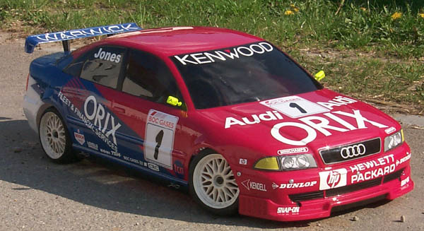 |
Bild 4 |
Multi-colored designs (Picture 6)
If you want to go for a multi-colored paint job you must watch for a few more details to make it come out like you
really want. Basically, the following rule applies when painting multiple color polycarbonate body shells:
start with the darkest paint and finish with the lightest one, otherwise the dark color shines through and
hampers the appearance. It is important to note that gradients are almost impossible to achieve with spray cans.
This is due to the fact that the spray cone of a can is not exactly confined. The unwanted overspray will
contaminate the entire body shell and will always be visible afterwards. Any attempts to remove overspray basically
fail because you‘ll never remove everything; or if you do you‘ll end up with a sharp edge instead of a nice
gradient. Sharp color edges don‘t have this problem, because you only need to mask the area which shall not be
painted.
As the design has been thought out before, you can draw the contours of the color edges on the outside using a
removable felt tip marker. (Picture 4)
If despite all precautions, an accident has happened, a paint killer will help.
However, as good polycarbonate paint tends to dye the plastic to some degree, a 100% removal is almost impossible.
Masking the color edges
Apply the masking tape to the edges with a little overhang. Again, this should be done without any
wrinkles.
At corners, edges or trim lines make sure that the tape really everywhere adheres to the body shell and does not
protrude from the surface. Otherwise, the paint will creep under it.
Now, simply hold the body shell against the light and see the previously applied markings shine through. Along these
lines carefully cut the masking tape with a sharp blade and then remove that side of the masking tape that will be
painted with the darkest color.
Virtually everything else must be masked or the fine paint mist will find a way penetrate through every
remaining crack. Potential fingerprints must be removed with some isopropyl or cleaner's naphtha.
Cut out windows, mounting holes a.s.o. must be sealed with masking tape from the outside, so that no spray will come
through.
The protective sheet will no be placed on the body shell again (where applicable). All areas not covered by the
sheet are taped with masking
tape, as well as the edges of the body (wheel arches, sills, etc.).
The tape should extend about 1 cm above the edge, but should not bend or adhere to the inside. The milky transparent
protective film does not need further treatment, except at points where the film is slightly peeled off.
After a final check of the edges of the windowpane masking, it can really start now.
Paint preparation
The paint needs preparation too:
In addition to the desired colors you should have.
- A hairdryer or a pot of heated water. Use either of them to warm the can(s) to a temperature of 40-45 ° C prior use. This is an advice for the perfectionists. Normal room temperature actually works without problems.
Applying the paint
Maintain a distance of about 30 cm between can and body shell. A closer distance may cause the paint to run. The
first coat should only be a very light but uniform. Allow to dry for about 5 minutes only and then apply additional
light coats in a cross pattern.
After each coat you should wait for about 3 minutes and then apply the next coat. The previous coat must not shine
wet, that‘s a sign for there‘s too much paint applied at once. The paint should also not be dried thoroughly.
For large areas such as hood, roof, etc. it must be ensured that do not apply too much paint at the turning points
where you change the movement of the spray. Otherwise you could see color differences from the outside.
Such irregularities can be detected easily by holding the body against the light; insufficiently painted sections
become visible and should be rectified.
When the paint application is finished and everything is ok the masking tape can be removed 5-15 min later. This
must be done very carefully, because the paint is still not already thoroughly dried. So, do not touch paint!
Now any small mistakes will be corrected by scraping small areas with a blade, wiping with an isopropyl or cleaner‘s
naphtha cotton swab or removing with paint killer.
Now that the entire masking was removed, you can cautiously start with the masking for the next color. This
procedure will be repeated for all remaining colors to be used.
When all colors have been applied, they may be backed up with RC 0710 white.
This improves the brilliance of the color. For metallic colors, backing with RC 0933 silver
is recommended to enhance the desired metallic effect; fluorescent colors must have a RC 0710 white backing to get the "bright effect".
It also prevents the shine through in light colors when you use window tint paint.
If the windows shall remain entirely clear the outside coverage can also be removed. This must be done carefully as
well, because otherwise parts of the masking tape might find their way into the freshly painted section.
If you prefer to tint (RC 0419) the windows just leave the outside coverage in place.
Hints on translucent polycarbonate colors
Translucent colors are tinted clear coats which are used to realize paint jobs with stunning looks, e.g. RC-Paint RC 0940 and 0941.
When preparing the body shell surface it must be ensured that no deep scratches occur during sanding or masking,
they would be definitely be visible in the paint later.
It is important to make sure that the translucent paint is applied equally and evenly everywhere to avoid color
differences.
The colors are applied in several thin coats until the desired thickness is reached. If these colors are used
without a backing coat of a solid color, they remain transparent, but colored in the respective choice of color.
This method is great for turn signals, taillights, window tint, or similar tasks.
This step of the painting should be laid entirely at the end of the paint job, as it is otherwise not possible to
realize, or only with a lot of masking.
The different results you can achieve with these colors by using various other opaque colors for a backing coat are
very diverse. They should only be made after painting a trial application on a piece of scrap polycarbonate to check
whether the results please you.
For example: with RC 0933 silver backing you‘ll get a pearl effect, RC 0710 white backing results in a “normal” color. In general,
the thicker the translucent color layer, the more intense and darker the color achieved.
Window tinting
The RC 0419 window tint should be applied at the earliest after about half an hour,
otherwise the lower paint coats may be dissolved again. Light colors should be masked because otherwise the tint may
show through.
For window tinting apply only very light coats, otherwise the tint will quickly become patchy. One must also be
careful to not apply too many coats or you‘ll end up with black windows.
Check from time to time, as in most cases 3-4 coats will be enough. Now the all masking and coverage can be removed.
Carefully, of course, because the color is still not yet completely dry.
When the paint job is finished let the paint dry for at least 6 hours, 24 hours are even better. Otherwise, the
paint could be scratched easily
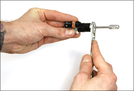
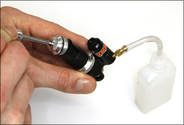
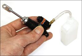
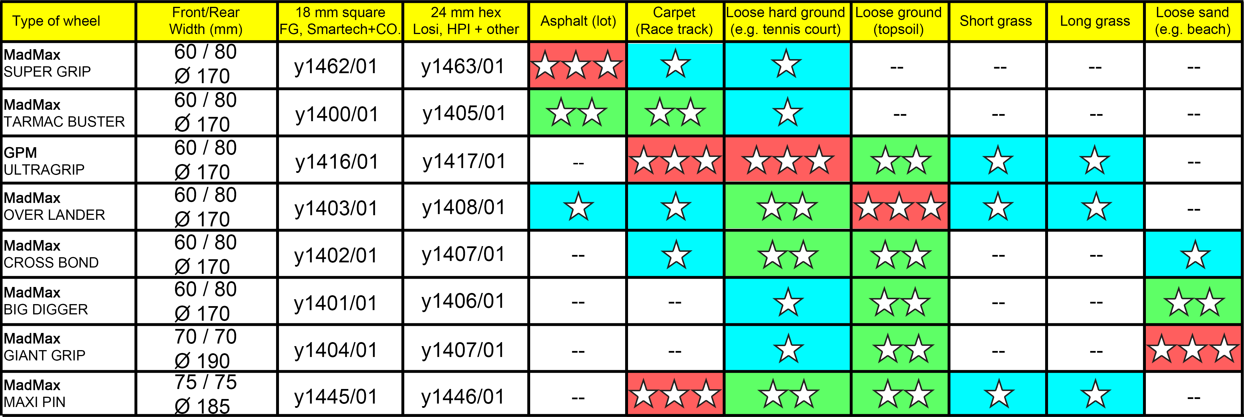
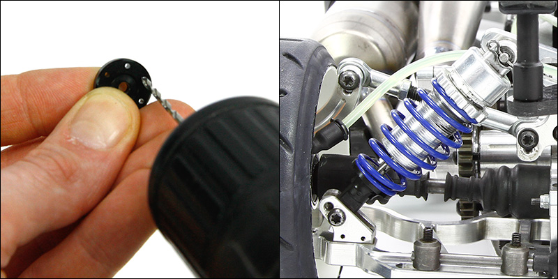
 Remove the bleeding nipple with tube and close the shock by means of the bleeding screw.